Discover our comprehensive guide on steel flanges, designed to provide you with a deep understanding of what steel flanges are and how they can be selected based on your specific application needs.
Steel flanges are typically connected to other pipe fittings using welding attachments and sealed together using bolts and gaskets. These essential components are widely used in industrial processes, such as in water pipelines, oil filtration machinery, food processing equipment, and pressure vessels, among others.
Over the years, various specifications have been developed for these industrial elements, each playing a crucial role across different sectors.
Ensuring that pipes remain securely connected is vital to prevent leaks in the piping system. Flanges help maintain accurate connections and ensure safe operation over an extended period.
Table of contents
- Steel Flanges Specification
- Different Types of Flanges
- Steel Pipe Flange Material Grades
- Galvanized Pipe Flange Working Pressure
- Steel Flange Dimension Chart
- WNRF Flange Weight Chart
- Steel Flange Face Types
- Reducing Weld Neck Flange Thickness Chart
- Steel Pipe Flange Pipe Flange Torque Chart
- Weld Neck Pipe Flange Bolt Chart
Steel Flanges Specification
| Steel Flanges Size |
|
|---|---|
| Flange Face Types |
|
| WNRF Flange Standards |
|
| Steel Pipe Flange Pressure class |
|
| Steel Flanges Types |
|
| Steel Flanges Manufacturer in India, Buy Weld Neck and Galvanized Pipe Flange in Different Sizes at Lowest Price in India | |

Manufacturing standard of pipe flanges is ASME B16.5
This standard includes NPS ½ to NPS 24 metric inches, covering pressure-temperature ratings, dimensions, tolerances, materials, sizes, tolerances, marking, testing, and opening methods of flanges.
The flange class rating includes 150, 300, 400, 600, 900, and 1500, available in sizes from NPS ½ to NPS 24 metric inches. Class 2500 is available up to NPS 12, with bolt diameters and flange bolt holes specified in inch units.
ASME B16.5 flanges are made from forged or cast materials. Blind flanges and certain reducing flanges are fabricated from forged, cast, or plate materials. This standard also includes requirements and recommendations regarding flange bolting, gaskets, and joints.
Different Types of Flanges
| Weld Neck Flanges | 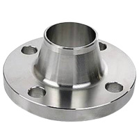 |
|
|---|---|---|
| Slip On Flanges | 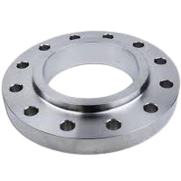 |
|
| Socket Weld Flanges | 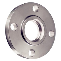 |
|
| Lap Joint Flanges | 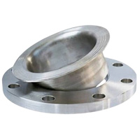 |
|
| Threaded Flange | 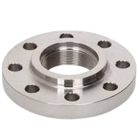 |
|
| Blind Flange | 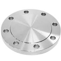 |
|
| Orifice Flange | 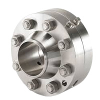 |
|
| Long Welding Neck Flange | 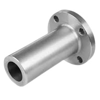 |
|
| Weldoflange and Nipoflange | 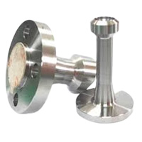 |
|
| Expander and Reducing Flange | 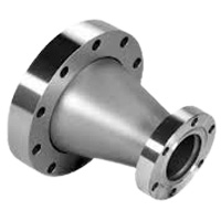 |
|
Steel Pipe Flange Material Grades
| Material | Grades | Features |
|---|---|---|
| Carbon steel |
|
|
| Stainless steel |
|
|
| Alloy steel |
|
|
| Duplex |
|
|
| Super duplex |
|
|
| Nickel Alloys Flanges |
|
|
Reducing weld neck flange have pressure rating of class 150 to class 2500
ASME creates the flange class, taking into account there are several pressure and temperature ratings. There are seven classes i.e. 150, 300, 400, 600, 900, 1500 and 2500. And the reducing weld neck flange can be worked at this pressure rating of class. The pressure rating specifies the highest tolerable pressure at a stated temperature. For instance, a class 2500 flange can resist more pressure and it is heavier compared to 1500 flange. Here, the class 2500 flange signifies that the flange is workable at this rated temperature without getting crack or damaged.
Galvanized Pipe Flange Working Pressure

| Working Pressure Bar [psi] | ||||||||||||
|---|---|---|---|---|---|---|---|---|---|---|---|---|
| Temp (°C) | (°F) | 29 – 38 | (-20.2 – 100) | 50 | -122 | 100 | -212 | 150 | -302 | 200 | -392 | 250 |
| Class | 150 | 19.6 | -284 | 19.2 | -278 | 17.7 | -257 | 15.8 | -229 | 13.8 | -200 | 12.1 |
| 300 | 51.1 | -741 | 50.1 | -723 | 46.6 | -675 | 45.1 | -654 | 43.8 | -635 | 41.9 | |
| 400 | 68.1 | -987 | 66.8 | -968 | 62.1 | -900 | 60.1 | -871 | 58.4 | -846 | 55.9 | |
| 600 | 102.1 | -1480 | 100.2 | -1452 | 93.2 | -1351 | 90.2 | -1307 | 87.6 | -1270 | 83.9 | |
| 900 | 153.2 | -2220 | 150.4 | -2180 | 139.8 | -2026 | 135.2 | -1959 | 131.4 | -1904 | 125.8 | |
| 1500 | 255.3 | -3700 | 250.6 | -3632 | 233 | -3377 | 225.4 | -3267 | 219 | -3174 | 209.7 | |
| 2500 | 425.5 | -6167 | 417.7 | -6054 | 388.3 | -5628 | 375.6 | -5443 | 365 | -5290 | 349.5 | |
| Temp (°C) | (°F) | -482 | 300 | -572 | 325 | -617 | 350 | -662 | 375 | -707 | 400 | -752 |
| Class | 150 | -175 | 10.2 | -148 | 9.3 | -135 | 8.4 | -122 | 7.4 | -107 | 6.5 | -94.2 |
| 300 | -607 | 39.8 | -577 | 38.7 | -561 | 37.6 | -545 | 36.4 | -528 | 34.7 | -503 | |
| 400 | -810 | 53.1 | -770 | 51.6 | -748 | 50.1 | -726 | 48.5 | -703 | 46.3 | -671 | |
| 600 | -1216 | 79.6 | -1154 | 77.4 | -1122 | 75.1 | -1088 | 72.7 | -1054 | 69.4 | -1006 | |
| 900 | -1823 | 119.5 | -1732 | 116.1 | -1683 | 112.7 | -1633 | 109.1 | -1581 | 104.2 | -1510 | |
| 1500 | -3039 | 199.1 | -2886 | 193.6 | -2806 | 187.8 | -2722 | 181.8 | -2635 | 173.6 | -2516 | |
| 2500 | -5065 | 331.8 | -4809 | 322.6 | -4675 | 313 | -4536 | 303.1 | -4393 | 289.3 | -4193 | |
Standard size range of socket weld and slip on flanges is 1/2″ to 24″
The standard size range for socket weld and slip on flanges is important for various industries as it provides fastening for the piping system. Socket weld and slip on flanges are typically manufactured in the standard size range from ½†to 24â€.
Understanding the categorization and differences between flanges across countries is essential for seamless integration and consistency in global projects.
Flange standardization ensures safety and uniformity across a broad range of global industries. It facilitates international trade by providing a common base for fabricators, suppliers, and consumers.
Steel Flange Dimension Chart

| NPS | 01/2 | 03/4 | 1 | 1 1/ 2 | 2 | 3 | 4 | 5 | 6 |
|---|---|---|---|---|---|---|---|---|---|
| O.D.(Inch) | 3.5 | 3.88 | 4.25 | 5 | 6 | 7.5 | 9 | 10 | 11 |
| SORF Bore Inner Dia (MM) | 9.65 | 11.17 | 34.54 | 49.53 | 61.97 | 90.67 | 116.07 | 143.7 | 170.68 |
| Bolt Holes No | 4 | 4 | 4 | 4 | 4 | 4 | 8 | 8 | 8 |
| Holes Dia (MM) | 15.74 | 15.74 | 15.74 | 15.74 | 19.05 | 19.05 | 19.05 | 22.35 | 22.35 |
| Bolt Circle (Inch) | 2.38 | 2.75 | 3.12 | 3.88 | 4.75 | 6 | 7.5 | 8.5 | 9.5 |
| WNRF Bore Inner Dia (MM) | 22.35 | 27.68 | 26.67 | 40.89 | 52.57 | 77.97 | 102.36 | 128.2 | 154.17 |
| Dia Hub Base (Inch) | 15.74 | 20.82 | 1.94 | 2.56 | 3.06 | 4.25 | 5.31 | 6.44 | 7.56 |
| Min WT (MM) | 1.19 | 1.5 | 12.7 | 15.74 | 17.52 | 22.35 | 22.35 | 22.35 | 23.87 |
| RF Dia(Inch) | 1.38 | 1.69 | 2 | 2.88 | 3.62 | 5 | 6.19 | 7.31 | 8.5 |
| NPS | 8 | 10 | 12 | 16 | 18 | 20 | 22 | 24 | |
| O.D.(Inch) | 13.5 | 16 | 19 | 23.5 | 25 | 27.5 | 29.5 | 32 | |
| SORF Bore Inner Dia (MM) | 221.48 | 276.35 | 327.15 | 410.46 | 461.77 | 513.08 | 564.38 | 615.95 | |
| Bolt Holes No | 8 | 12 | 12 | 16 | 16 | 20 | 20 | 20 | |
| Holes Dia (MM) | 22.35 | 25.4 | 25.4 | 28.44 | 31.75 | 31.75 | 35.05 | 35.05 | |
| Bolt Circle (Inch) | 11.75 | 14.25 | 17 | 21.25 | 22.75 | 25 | 27.25 | 29.5 | |
| WNRF Bore Inner Dia (MM) | 202.69 | 254.5 | 304.8 | 387.35 | 438.15 | 488.95 | 539.75 | 590.55 | |
| Dia Hub Base (Inch) | 9.69 | 12 | 14.38 | 18 | 19.88 | 22 | 24.25 | 26.12 | |
| Min WT (MM) | 26.92 | 28.44 | 30.22 | 35.05 | 38.1 | 41.14 | 44.45 | 45.97 | |
| RF Dia(Inch) | 10.62 | 12.75 | 15 | 18.5 | 21 | 23 | 25.25 | 27.25 |
WNRF Flange Weight Chart
| NPS | 1/2 | 3/4 | 1 | 1¼ | 1½ | 2 | 3 | 4 | 5 |
|---|---|---|---|---|---|---|---|---|---|
| WNRF (KG) | 0.9 | 0.9 | 1.4 | 1.4 | 1.8 | 2.7 | 5.2 | 7.4 | 9.5 |
| SORF (LBS) | 1.1 | 1.98 | 1.98 | 3.08 | 3.08 | 5.07 | 9.03 | 13 | 14.99 |
| BRF (LBS) | 1.98 | 1.98 | 1.98 | 3.08 | 3.96 | 5.07 | 9.03 | 16.97 | 19.84 |
| NPT (KG) | 0.5 | 0.9 | 0.9 | 1.4 | 1.4 | 2.3 | 4.1 | 5.9 | 6.8 |
| LJRF (KG) | 0.5 | 0.9 | 0.9 | 1.4 | 1.4 | 2.3 | 4.1 | 5.9 | 6.8 |
| SWRF (LBS) | 1.98 | 1.98 | 1.98 | 3.08 | 3.08 | 5.07 | 9.03 | 13 | 14.99 |
| NPS | 6 | 8 | 12 | 14 | 16 | 18 | 20 | 22 | 24 |
| WNRF (KG) | 11.7 | 18.9 | 39.6 | 51.3 | 63 | 74.3 | 88.7 | 101.3 | 120.6 |
| SORF (LBS) | 18.95 | 29.76 | 63.49 | 89.28 | 105.16 | 128.97 | 163.8 | 183.64 | 218.25 |
| BRF (LBS) | 26.89 | 46.73 | 122.13 | 138.8 | 178.57 | 218.25 | 282 Mold design and manufacturing services for cosmetic bottle cap mould, Drinks Cap Mold, Condiment Bottle Cap Mould, flip top cap mold and other series of products. We are a company specializing in bottle cap injection mould manufacturing and injection molding production, with many years of industry experience and a highly skilled team.
When it comes to bottle cap injection mold making, we pay attention to details and innovation to ensure that every mold meets high standards of quality. Our mold design team can carry out precise designs based on customer needs and product characteristics to ensure that the mold has a reasonable structure, high precision and strong durability. At the same time, we use advanced manufacturing technology and equipment to ensure that every aspect of mold manufacturing is strictly controlled, thereby providing customers with high-quality bottle cap injection molds.
In terms of injection molding production, we have advanced injection molding equipment that can meet the production needs of different scales and types of bottle caps. Our injection molding technology is exquisite, which can ensure the stable quality, accurate size and beautiful appearance of the bottle caps. In addition, we also focus on environmental protection and energy conservation, and reduce energy consumption and environmental pollution by optimizing production processes and equipment.
In addition to regular bottle cap products, we are also good at manufacturing flip caps and other caps with special functions or designs. Our technical team is able to provide customers with personalized customized services, designing and manufacturing according to customer needs to meet the diverse needs of the market. caps mould,caps injection mould,bottle Caps injection Mould,caps plastic injection mould,caps mold Dongguan Hongke Plastic Precision Mould Co.,Limited , https://www.hongkemold.com |